Investigation of RC Shear Wall Dimensions and Arrangement On the RC Structure Seismic Behavior
Ali Ghasemzadeh1 * and Behzad Talaei Taba1
http://dx.doi.org/10.12944/CWE.10.Special-Issue1.141
The novel goal of this study is to investigate shear wall dimensions and arrangement on the seismic behavior of a reinforced concrete structure. To achieve the goal, an eight story concrete structure was modeled using nonlinear finite element software. Nonlinear time history dynamic analysis according to 2800 code used. Northridge acceleration was applied on the structure. Usual dead load and live load were also applied on the stories surface. Shear walls with 3 meters and 5 meters length were placed in four different arrangement, therefore totally eight models have been created. Maximum displacement of structure and absorbed base shear by walls will be discussed. Results generally showed that when shear wall length increases, absorbed base shear by shear wall and maximum displacement of the highest story increase too.
Copy the following to cite this article:
Ghasemzadeh A, Taba B. T. Strategic Vision of Qazvin's Traditional Orchards. Special Issue of Curr World Environ 2015;10(Special Issue May 2015). DOI:http://dx.doi.org/10.12944/CWE.10.Special-Issue1.141
Copy the following to cite this URL:
GHasemzadeh A, Taba B. T. Strategic Vision of Qazvin's Traditional Orchards. Special Issue of Curr World Environ 2015;10(Special Issue May 2015). Available from: http://www.cwejournal.org/?p=11705
Download article (pdf)
Citation Manager
Publish History
Introduction
Moment resistance frame, bracing frame and shear wall are the most common systems which are used to resist lateral forces in a structure. Research show that using shear wall and moment resistance frame together in a structure can be effective more than other systems. In this system both of shear wall and moment resistance frame can affect each other and also they have advantages of shear wall and moment resistance frame. In this system, shear wall resists lateral forces while moment resistance frame resists gravity forces. Dimensions and arrangement of shear walls are the most important part of concrete structure design which can reduce overturning risk and element (such as beam and column) dimensions (Talaii Taba, 2010).
Shear wall is the most important element of a concrete structure which could improve seismic behavior of a structure by resisting lateral loads. Shear wall is a vertical RC shell which is transversally and longitudinally reinforced so that the steel bars continue from the foundation to the top level of wall (Ching et al, 2006). As shown in figure 1, shear wall performs as a contriver column. In fact shear wall increases structure stability by resisting shear and moments due to lateral forces such as wind or earthquake.
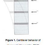 |
Figure 1: Cantilever behavior of shear wall (Kheyroddin, 2010) Click here to View figure |
Using shear wall in a 30 to 40-story buildings can be economical. In the buildings with more than 40 stories, shear wall width will be so great to resist stresses of wind and earthquake loads that using it would not be economical (Kheyroddin, 2010). So moment resistance frame or dual systems (like as moment resistance frame and shear wall together) can be used in the buildings with more than 40 stories. According to 2800 code, the maximum allowable height for structures which are located in high seismic zone risk and low seismic zone risk is 70 meters and 200 meters, respectively.
As mentioned before, the most effective lateral loads resisting system, is dual system including shear walls and moment resistance frame. That’s because using shear wall or brace in a structure, can control structure lateral displacement by increasing structure stiffness. Shear wall or brace, also can resist major lateral forces applied to the structure due to earthquake or wind.
2800 Code Requirements for 3d Dynamic Analysis
In this section, 2800 code requirements for three dimensional dynamic analysis is going to be presented. In the time history analysis, at least three couples of accelerators regarding the zone shall be considered. All of the accelerators shall be scaled to the maximum acceleration. In other words, the maximum acceleration of each accelerator shall be equal to “g”. The response of each couple accelerator shall be mixed together using SRSS[1] method to make a single mixed spectrum for each couple accelerator. Scale factor which is multiplied in the accelerator shall be chosen so that the average of mixed spectrum in the period range from 0.2T to 1.5T be less than 1.4 times of the related spectrum in the standard spectrum.
After scaling accelerators, each couple accelerator is applied to the structure in two directions at the same time (as figure 2 shows). Response of the structure will be determined as a time equation. Final structure response in every time, is equal to the maximum response obtained in the analysis using three couples of accelerators.
[1] Square Root Sum of the Squares
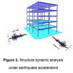 |
Figure 2: Structure dynamic analysis under earthquake accelerators Click here to View figure |
It should be mentioned that, according to 2800 code, if seven accelerators are used instead of three accelerators, the average of responses can be considered as final structure response.
Loading
Dead load and live load were applied on the floor of each story in size of 600 kg/m2 and 500 kg/m2, respectively. Dead load due to structure elements weight was considered by the finite element software. Acceleration of Northridge earthquake which is scaled according to 2800 code is applied to the structure. Northridge acceleration is shown in the figure 3.
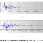 |
Figure 3: Northridge Acceleration a) longitudinal direction, b) transverse direction Click here to View figure |
Geometry of Beams, Columns and Shear Walls
In this section, characteristics of models such as beam and column dimensions, wall arrangements and etc. will be presented.
Beam, Column and Shear Wall Dimensions
Dimensions of structure elements (beams, columns and shear walls) were chosen according to dimensions which are used in common buildings. It should be mentioned that dimensions of 5, 6, 7 and 8 stories elements were chosen smaller than bottom stories elements to reduce dead load due to concrete weight. Dimensions and reinforcement of structure elements used in the models were as table1.
Table 1: Characteristics of numerical models
|
element type |
section |
longitudinal reinforcement |
transverse reinforcement |
|
|
stories 1, 2, 3, 4 |
beam |
B50X55 |
- |
- |
|
column |
C50X50 |
12Ø20 |
Ø10@15 cm |
|
|
shear wall |
W25 |
Ø12@15 cm |
Ø12@15 cm |
|
|
boundary element reinforcing |
c50x50 |
12Ø25 |
Ø10@15 cm |
|
|
stories 5, 6, 7, 8 |
beam |
B40X45 |
- |
- |
|
column |
C40X40 |
12Ø18 |
Ø10@15 cm |
|
|
shear wall |
W20 |
Ø12@15 cm |
Ø12@20 cm |
|
|
boundary element reinforcing |
c40x40 |
12Ø20 |
Ø10@15 cm |
Shear Wall Arrangements
In this study, four different arrangements for shear walls placing in the structure were considered. Moreover shear walls were modeled in two different lengths (three meters and five meters). Figure 4 shows the shear walls arrangements.
Results and Discussion
The main goal of this study is to investigate the effect of RC shear walls dimensions and arrangements on the seismic behavior of RC structure. In this section, the results obtained from nonlinear finite element software are presented. Results can be classified in two main parts: a) absorbed base shear by shear walls b) maximum displacement of structure area center for each model.
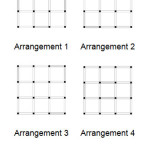 |
Figure 4: Shear wall arrangements Click here to View figure |
Absorbed Base Shear
Five-Meter Shear Walls
Table 2 presents absorbed base shear by the five-meter shear walls which are located in four different arrangements in each story.
Table 2: Absorbed base shear by five meters shear walls
|
Arrangement 1 |
Arrangement 2 |
Arrangement 3 |
Arrangement 4 |
|
|
Ground floor |
1299460 |
1198148 |
1161535 |
1369729 |
|
Story 1 |
1181566 |
1070940 |
1043138 |
1228925 |
|
Story 2 |
1006630 |
910934 |
867340 |
1060252 |
|
Story 3 |
826309 |
763486 |
675978 |
929464 |
|
Story 4 |
813145 |
751636 |
682762 |
887388 |
|
Story 5 |
675682 |
601141 |
555433 |
722480 |
|
Story 6 |
472299 |
421641 |
396311 |
512408 |
|
Story 7 |
192059 |
166701 |
159395 |
221439 |
|
Story 8 |
0 |
0 |
0 |
0 |
To have a better comparison for absorbed base shear wall in each arrangement, figure 5 is presented.
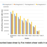 |
Figure 5: Absorbed base shear by five meters shear walls in each story (ton) Click here to View figure |
As figure 5 shows, absorbed base shear by walls in arrangement 4 with the average of 89.11% is greater than other arrangements. Absorbed base shear by shear walls in arrangements 1, 2 and 3 are 68.68, 85.93 and 82.45 percent of total absorbed base shear by the structure, respectively.
Three-Meter Shear Walls
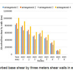
Table 3 presents absorbed base shear by the three-meter shear walls which are located in four different arrangements in each story.
Table 3: Absorbed base shear by 3 meters shear walls
|
Arrangement 1 |
Arrangement 2 |
Arrangement 3 |
Arrangement 4 |
|
|
Ground floor |
822362 |
863475 |
707140 |
1011179 |
|
Story 1 |
761014 |
797082 |
666596 |
917400 |
|
Story 2 |
641926 |
679183 |
554895 |
775672 |
|
Story 3 |
494366 |
521434 |
416901 |
616275 |
|
Story 4 |
559610 |
593536 |
492484 |
662687 |
|
Story 5 |
442919 |
475286 |
389252 |
542388 |
|
Story 6 |
305953 |
329583 |
264481 |
380127 |
|
Story 7 |
97099 |
113577 |
81815 |
142297 |
|
Story 8 |
0 |
0 |
0 |
0 |
Figure 6 shows the column chart diagram which is presented to compare absorbed base shear by three-meter shear walls in four different arrangements.
 |
|
As figure 6 indicates, the most absorbed base shear belongs to arrangement 4 by the average of 72.31%. Absorbed base shear by shear wall in arrangement 1, 2 and 3 are 66.49, 66.92 and 62.40 percent of total absorbed base shear by structure, respectively.
Maximum Displacement of Structure Area Center for Each Model:
Five-Meter Shear Wall
Figure 7 shows the maximum displacement of structure area center for each arrangement in eight-story building with five-meter shear walls.
As figure 7 shows, the maximum displacement of structure area center for the models are 17.81 cm, 14.09 cm, 16.3 cm and 15.4 cm in arrangement 1, 2, 3 and 4, respectively. The maximum displacement belongs to arrangement 1 and is 3.72cm, 1.51cm and 2.41cm greater than arrangements 2, 3 and 4.
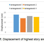 |
Figure 7: Displacement of highest story area center Click here to View figure |
Three-Meter Shear Wall
Figure 8 shows the maximum displacement of structure area center for each arrangement in eight-story building with five-meter shear walls.
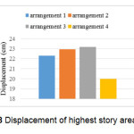 |
Figure 8: Displacement of highest story area center Click here to View figure |
As figure 8 shows, the maximum displacement of structure area center for the models are 22.29 cm, 22.93 cm, 23.18 cm and 19.98 cm in arrangement 1, 2, 3 and 4, respectively. The maximum displacement belongs to arrangement 3 and is 0.89cm, 0.25cm and 3.2cm greater than arrangement 1, 2 and 4.
Conclusions
To investigate the effect of RC shear wall dimensions and arrangements on the seismic behavior of RC structure an eight story concrete structure was modeled using nonlinear finite element software. Northridge acceleration was applied to the structure. Following conclusions can be driven from results obtained in section 5.
- When shear wall length increases, absorbed base shear by shear wall increases too.
- Placing shear walls in the inner axes of a structure, can increase absorbed base shear by shear walls.
- Any increase in shear wall length, increases the maximum displacement of area center of the highest story.
References
- Ching, F. D., Faia, R., S., and Winkel, P. (2006). Building Codes Illustrated: A Guide to Understanding International Building Code (Building Codes Illustrated) (2th Ed.). New York, NY: Wiley.
- Kheyroddin, A. (2010), “Design Of RC Shear Walls”.
- Structure Seismic Design, 2th edition, 2800 code, (1999).
- Talaii Taba, B. and Arshian, A. (2010), “Design of Reinforced Concrete structures”